Saturday, December 19, 2015

Build an active receive antenna..... The Mini-Whip.....

So I was browsing the dutch variety of eBay... called marketplace... (no i am not kidding)....
And all of a sudden I stumbled on an advert with a PCB+components for a mini-whip....

Now, as I wanted to build one for a while, but did not feel like going through the trouble building my own PCB's, so I ordered a kit at this webshop....


It's a very simple and basic kit.... So out came the components and the soldering iron was turned on....


The PCB's are very nice... BUT!, i was taught that you should never use 90 degree corners, but use 2 of 45 degrees instead. I was told that it is wise to keep the actual antenna part as close to the gate of the J310. and although it is close, i can see some small improvements in the layout of the PCB.
But, don't get me wrong, it's a  very nice PCB!

So after a few minutes......


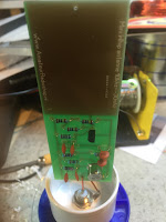
There are not that many components so it did not take me too long....
One thing to remember is that the PSU PCB needs to be soldered on 2 sides!
Hopefully you can see the soldering of the C's on the upper layer of the PCB....

So all was left was to put all in a housing and start to test this antenna.....

I found a very nice housing for the PSU at a fair.....


So I hooked everything up and started to test the reception of the Mini-Whip....

I made a short video of some CW i found on 40m. There was not much going on on other bands...
Propagation was bad, and the time i was listening was not that great either.....
Ant1 is the Falcon out-250b (outside) and Ant2 is the Mini-Whip behind a double window, inside , close to my switching power supplies...... Not the best place :)


So my conclusion was..... I am amazed.... Yes the base noise level is a bit higher, but the signal is as good as my outside antenna! And the mini-whip is not at a good spot at all....
The mini-whip will go outside somewhere away from the house. which probably will be good for the noise level.

Tuesday, September 22, 2015

New toy: ZD-985 desoldering station.... Part2

Hello all, 

So today I finally cleaned my workbench and installed the ZD-985 desoldering station.....
The absolute first impression I got was: "O.M.G. its big!!" and however this sometimes is good, this time I was less amused. It is really bulky compared to my other soldering stations...

It will not fit under my shelve!!!
The unit itself, so not the holder, is 17 cm high, 13 cm wide and 16 cm deep.
For my non metrical friends.... 6.7 inch high, 5,1 inch wide and 6.3inch deep... (if this is wrong, please don't blame me, but blame google for finding me a crappy only converter :) )

So whats in the package.....


Well off course the unit itself..... but it also comes with.....

- Some spare desoldering tips in different sizes.
- Spare filters in different sizes. (3 for the desoldering gun, and 1 for the main unit)


- A Manual in German and English
- A service manual
- 3 different sized cleaning rods.


The cleaning rods actually are labeled A, B and C.... but the tips aren't.... So I guess you need to find out which to use for which tip... Not too hard I think....
They actually look quite nice and the end is processed so you can get the sticky bits out without a problem....


So let's take this baby for a test drive......
The test print to be desoldered.... A standard PCB, nothing fancy... quite old...


So i turned on the unit, had to wait a few seconds till it reached operating temperature, and about 5 minutes later it looked like this.....


The unit is light and the cable and tube are flexible so they do not start to irritate you after 2 seconds because it pulls you away from where you want to go.....
The solder pads and the components are both clean.... I kinda expected the unit to fail a bit here due to low vacuum pressure... but it did not.... it looks perfect..... I took a picture through a magnifying glass to check.... but this just looks perfect to me....


So all good ? no, not all good.... 
The Cable and vacuum tube don't come with a few clips to keep them together. Not necessary, but would have been nice.

One other thing that I don't like (this is totally my opinion), is the desoldering iron itself... It's ergonomics are making you hold it in a position which to me is weird when the PCB is too flat on your workspace.

And this is because it looks like a gun.. (maybe my friends in Texas are more used to this  ;) )
Weller solves this problem better I think , and it is probably not that hard to build it like this....
Maybe it is a copyright thing (But then again, since when does that stop our Asian friends to produce it anyway....)


 So..... Let's add things up.... starting with the cons....

CONS:
- Its a bit bulky....
- Ergonomics could have been better....
- No wraps to keep the vacuum tube and the cable together. 
- Compared to for example a Weller, the whole thing feels a LITTLE bit plasticy and light....
- No ESD connector...

PROS:
- It works like a charm.... results are just as nice as when i worked with a Weller at school and in a repair shop.
- It's light, so no fatigue when you have to work with it a lot
- IT IS CHEAP !!!!!!!
- and did i mention it is CHEAP!!!!

No Kidding , I found a Weller discount store, and they charge 1109 euro's for a basic Weller station, the WR-2002D. A desolder station that does EXACTLY the same as the ZD-985.....
They do give a 10% discount... but that is still 995 euro's 
The ZD-985 was 129 Euro's including shipping.....

CONCLUSION:
So to conclude this review.... I already stated in my previous post that the price/quality factor of this desolder station would be hard to beat. And in have to conclude that I was right... it's not...


There are some cons... but they are sooooo minor...
Add your own clips to keep the cable and vacuum tube together....
Add an ESD point to it yourself, it's not that hard.
Even me saying that the ergonomics are not that good is almost looking for a thing to be negative about, because when you work with this station, you will put it back into the holder a lot anyway to get the components of the PCB.

This desolder station has entered my shack.... and it's not leaving anymore.....

73's
Alex
PA1SBM


Tuesday, September 15, 2015

New toy: ZD-985 desoldering station.... Part1

Today the postal service delivered  a package.....
 Within was another box....


In that box was my brand new desoldering station.


It is the same as Dave from EEVBLOG talked about in this video
He was not too positive about the one he received.... His one did not heat up...
Worse, his tip did not open without the help of the cleaning tool which let me to believe that the suction power is not too good....
I want to state right now.... I did NOT have any of these problems.....
That makes me think Dave got a, what we call in holland, "monday morning item"
Lateron in his vlog he became a lot more positive, especially when he was using it......
His verdict was based on that you get a big bang for the buck.... Which I think will be my conclusion as well...

I turned it on  , and all worked straight out of the box.....


I ordered mine from a supplier on "marktplaats" which is like the dutch eBay.
After sending him an email I found out that I had actually met him at a dutch ham fair....
So I payed the invoice, a whole whopping 129 euro, and I received the desolder station today....

He added small gift as well......
Solderwick..... really... you can NEVER have enough of this stuff.... this works 100000 times better then the spring loaded sucker.... that one really sucks....

Next post I will write some about how i think it works.... but without a doubt i will find myself writing the same conclusion as David has in his vlog....

More to come sometime soon (few days... work will be busy today and tomorrow)

73's
Alex
PA1SBM

Monday, August 24, 2015

RS-232 disappearing from PC's and so is PCI.... so now what to do when you run Linux as a HAM?

Hello all,

Well, it's no surprise that I am a big fan of Linux. On my blog I usually post about Linux stuff often enough.

Recently I bought a new PC. I used an "old" AMD 64 X2 4000+ with 8GB DDR2 800MHz memory, and I thought I would spoil myself with a new one.
As it was going to run Linux , it did not need be top of the line, so I bought myself an Intel Core i7 with 16GB 1600Mhz memory.
And when it arrived I started to add my SSD to it, and installed it next to my desk.....

Now, as you might know, I use a Kenwood TS-480satt, still love it, and that uses a RS-232 bus to communicate to my PC (and so do most transceivers, as USB has just come to the very latest models of all normal brands). And for as far as i know, most rotators use rs232 as well. My old PC had 3 of those RS-232 ports as I added an PCI card with 2 extra ports.

Now... my new PC had.... NONE!!!...... So I thought that I would just add the PCI card to the new PC. CRAP!!.... it has no PCI buses either! So this card became useless.....


So I started to look on the one site that solves 99% of my problems... www.ebay.com
And I found myself a new PCI-e card.....


Now you have these in 2 and 4 ports , or 1 parallel and 2 serial ports......
And they claim that these work under Linux..... NO THEY WILL NOT... (at least not out of the box, and not without tinkering a lot on your system) They are not worth to do so anyway....

These cards use a chip-set called CH382L and those might work fine with a simple driver for windows(not tested), but for Linux they are a major pain up the a$$ as this chip-set has not found its way to the Linux kernel (yet).

I tried 2 nights in a row to fix this... no luck what so ever.... google did not help a lot either, it just came up with a lot of results of either not working solutions, or people like me searching for a solution....

So, now how to solve this..... EASY ... buy the proper chip-set....
I ordered a very nice version , with a breakout cable for 4, yes 4 serial ports. (and you have them for 8 ports as well)

The chip-set it uses is: MCS9904
And I bought it with this eBay seller... eBay seller "only" 24 euro's
There is also a MOSCHIP 9901 chip-set, for a 2 port version, which I GUESS will work too.
I did not test one (yet). Example: eBay seller

Now this MSC9904 chip-set does work out of the box when using Linux Mint 17.2 (so my best guess would be that Ubuntu and Debian will work as well as they are builds from the same Linux tree)


When using those cheap a$$ USB-RS232 cables, it usually means that as soon as you start to make a QSO , the cable malfunctions. this PCI-e card does not have any problem with that.

An other HAM, who tested one of my cables, said that this usually has to do with the harmonics of the used frequency being too close to the internal oscillator or the max232 ic used in the converter.
I personally think this could be solved with proper shielding and such, as my way too expensive cable has no problem with this for as far as i know.

So as a conclusion, as long as you buy the MSC9904 chip-set, you're good to go!
I noticed that if it has this chip-set, they will write it on the eBay page. I guess the sellers found out that Linux users are looking for this ;)
Yes, it is not as cheap as the others, but this at least works.....

Hopefully this will help you out when you buy a new PC without PCI and RS232 (which is basically any new PC you can buy these days.)
If any one found another chip-set that works, please do tell us in the comments!!

73's
Alex
PA1SBM

Sunday, August 16, 2015

A new PSU... KPO SPS-30-II ... PART 2: Installing the missing part

So I promised part 2 soon , so here it is :)

This week my order of 10 clixons (50c N.O.) arrived.....
And today i had time to add this to my latest PSU.....

So again i got rid of 13 screws....


And i looked at an empty spot where a clixon should be......


The holes you see there are only in the metal sheet they use for a heat sink... they are not drilled through.... which took me about a minute to fix.... 2 nice holes all the way through.....

I installed the clixon.....


You can see the slightly smaller black bolts i used to install the clixon. You would say this is as it came from the factory if you would not know better....

When wiring up everything, I noticed it that it would be better to rotate the fan 90 degrees, so the wire would exit the fan close to the clixon. (2nd picture)


The fan they use i this model is not (how surprising)  an expensive one.... I might replace in time with one which is better (at least one with a ball bearing)
I am not sure yet as it might also be handy to have a "noise" warning if it becomes too hot.


After that it was just a bit of soldering and the job was done.....


I put back the cover, screwed in 13 screws.... and reinstalled it on the shelf....
Again, I now have no fan noise if everything is in idle mode.... nice and quiet....

So from a silent shack, I wish you 73's!

Alex
PA1SBM

A new PSU... KPO SPS-30-II ... PART 1: The good, the bad and not so bad at all

A while back I bought a KPO SPS 30-II .... And I promised to write something about it in a few weeks... well.. a few weeks became a few months....

So without any more delay..... here it is , a 59 euro 30 amps power supply......
yeah you read it right... 59 euro..... (thats dirt ass cheap for dutch standards)

It looks like this.....


Not too bad in my opinion, nice clear meters, and if you take the price into account, it's beautiful.
It feels well build as well , as only the front s plastic, the rest is all metal....
It does have this nasty warning at the top back.....


I guess this is a bit over exaggerated as the construction will not allow this to become too hot... (airflow is continues, and the components are on the bottom and not at the top)

Soooooo.... Let's take a look inside....
Well yes.... not that quick though.... to get inside you need to take out  >>13<< screws.
My 1st thought was that this was a tad too much.... but no.... as soon as you have them all out you will notice that without the 13 screws, the structural integrity has completely gone... and it feels not well build at all anymore...  Not that this is a problem, i do not know any people that would take it apart, and then put it on a shelf to use it....


So now we can take a look inside....


At first glance, this PSU looks really nice... A bit like the other proper build KPO i wrote about earlier... No spilled heat paste or white glue stuff...
But after about 30 seconds i noticed a missing part..... AGAIN!!!


In the picture above, again, the clixon is not installed.... KPO clearly did want to put it in as the 2 holes give away their intentions.... (ohh by the way, the heat past you see in this pic, is the only you will find in this unit)
I do not know why they will not just add this.... the PSU is 59 euro, add the stupid thing and make it 64,95... still cheap...

So how does it perform... As I did not have time to have it run at high current for a while, I measured the DC voltage with no load (just 2 small vhf/uhf transceivers powered on) and 1 measurement with a load of around 8 amps....


As you can see , with 8 amps , the PSU drops 0.06 volts..... I think that this will do perfectly for all my VHF/UHF sets.... (I will measure some higher currents on all my PSU's in the near future)


Part 2 , adding the missing part will come soon :)

73's

Alex
PA1SBM


Saturday, August 15, 2015

The FoxDelta.com 1-50 MHz swr analyzer.........

A while back I was browsing the internet..... I always wanted a SWR analyser, but i always thought that the price was a bit high for a tool I only use like 5 times a year....
 So somehow I got to a site.... foxdelta.com ...... And I found this..... aaz-0914a
..... 50 bucks...... After like thinking about it for about a month, I ordered it....

Then after a few weeks....... No i have to be honest.... it was more like just over a week from the US/India to the Netherlands... nice and fast....


WOOHOOO!!! its here...... but then... ohh crap... real life.....

So after a month... I started to unpack it.... holly crap this is nice......


Every thing in zip-lock bags, even the PCB... and the PCB looks sweet as well.....
And oh crap again... real life.... Again a month later....
Finally some free time.... lets go !!!


And after about an hour or two we got a working project.....

Well, in this picture it was not working to be honest.... I kinda screwed up a C on the PCB... soldered it on the wrong spot... so no input signal came to the controller.
So this is when it was really done :)


And, as there is no OSX or Linux software yet to my knowledge (I will check up on this later), I had to steal my girlfriends windows 10 laptop.... she never noticed :).....

And then you get nice graphs.... like this.....


Now this is from my 10m antenna, which I thought to dip a little later in the band.... more around 28.450 MHz.... and I thought the SWR would be a little lower, but I never actually measured this at all.... So now I need a propper SWR meter.... guess I need to borrow one :)
If the analyzer is way off, I will post again , but I think it is not that far off to be honest...


73's
till later!!

Alex
PA1SBM